Pimp the Hardware
Do I need to do this modifications?
Under normal circumstances: No
Whenever you want to use OOBD with the DXM Bluetooth BTM222 or with any other similar device as a standard OBDII diagnostic device, you do not have to do these modifications!
These modifications are only needed in conjunction with the own OOBD firmware to use not only the build-in highspeed CAN bus, but also a second, OEM specific CAN bus on some other pins.
Disclaimer: Be aware that you loose all warranty on your device if you are doing this (or any other) modification. The OOBD Team does not take any warranty for any direct or indirect damage
Also this rework needs experience in soldering, this is nothing for beginners. So you are sure to want to do it?
Ok, let's start.
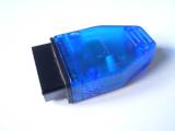
First you see the original DXM Bluetooth BTM222
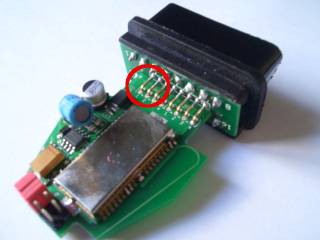
In there you'll find this pcb. The OBD connector pcb is connected to the main board with 8 jumpers. We'll concentrate on the two left most ones.
These two ones needs to be removed first. To do this, do as follows:
- cut the most left one with a small cutter in half
- while heating it with a small soldering iron, take one half of the jumper with a small pliers and pull it carefully out of the board
- then the same with the second half of the jumper
- and then the whole again with the other jumper
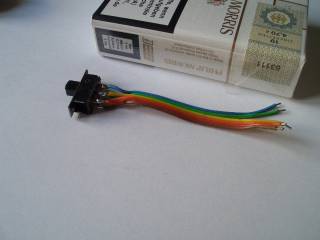
As next we prepare the bus switch (e.g. Sliding switch 2 x On/On 50 V/DC 0,5 A (Conrad Electronic)).
This picture here shows (at least for smokers) the dimension of the jumper wire
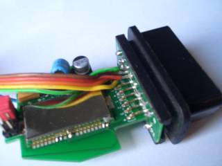
Now the most difficulty part comes. Assuming, we count the removed jumpers again from left to right and name the OBD- connector side as “OBD” and the PCB side as “PCB”, then the wire connections would be as follow:
| goes to | switch pin (faceview) | goes to | |
|---|---|---|---|
| OBD jumper 1 | 1 | 2 | OBD jumper 2 |
| PCB jumper 1 | 3 | 4 | PCB jumper 2 |
| OBD where ever your second CAN- High is connected | 5 | 6 | OBD where ever your second CAN- Low is connected |
These connections are difficulty to make, so you need a calm hand for doing this.
The next problem will be that there where the additional wires have been soldered onto the OBD PCB, the flange in the housing which stops the connector from moving will interfere with these new wires.
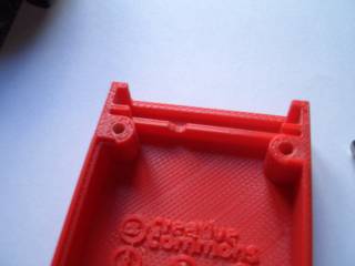
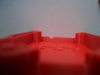
So depending on where your new pins are, you've to cut some small cutouts in these flange to make the housing fit again
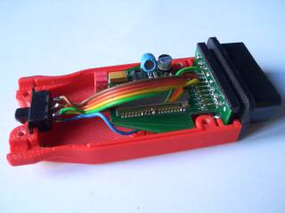
Then finally make sure that the new wires run smoothly through the housing and do not put pressure on the PCB or chafe on sharp edges.
That's it 
